Introduction
Power-up
The CPU Patch Panel
The pinout of the console cable
Console commands
Error codes
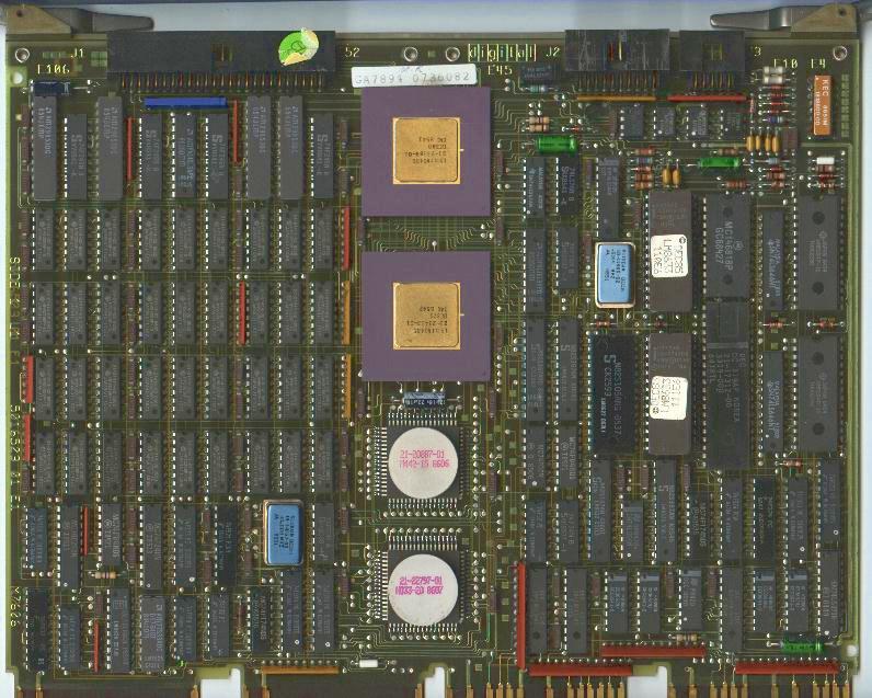
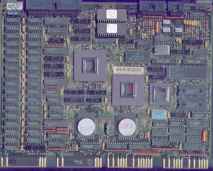
The KA630-A CPU modules were used in MicroVAX II systems, KA630-B's can be found in VAXstation II and VAXstation II/GPX machines. As you can see on the two pictures above, two PCB layouts were used: KA630-based systems shipped after 1st of February, 1987 are likely to contain the newer M7606 A1 revision. There are no functional differences between the cards. The difference between the KA630-AA and a KA630-AB is that the -AB doesn't contain the hardare floating point unit, instead, these instructions are supported through software emulation. The VAXstation is a MicroVAX II with a QVSS graphics module (VCB01), the VAXstation II/GPX is a a MicroVAX II with the QDSS (VCB02) graphics board-set. Both are one-user systems from the operating system side by default.
The KA630 CPU features LMI (Local Memory Interconnect), which uses three different paths to system memory: the qbus, the C-D interconnect of the backplane (thus it must be fitted into a Q22/CD backplane, which is usually a BA23 or BA123 enclosure with a "mixed" backplane), and a ribbon cable that connects the CPU module to MS630 or compatible third-party memory boards. This means, that you can use qbus memory cards in a MicroVAX II (although it results in weaker performance), or you can use LMI MicroVAX II memory modules. Do not try to use LMI memory modules intended for later MicroVAX systems (modules like the MS650-series, etc)! The CPU module should go into the first slot of the backplane, the LMI memory boards should be next (don't stuff more than 16 MBs of memory onto the bus, it won't work; don't insert MicroVAX II LMI memory modules into Q22/Q22 slots either).
The KA630 features:
The module has three connectors:
J1: memory interconnect cable
J2: CPU patch panel ("bulkhead panel") connector #1: LED
display and switches
J3: CPU patch panel ("bulkhead panel") connector #2: serial
line connector
All three cables are straight-through ribbon cables, nothing special.
Upon powering, the CPU enters one of the three boot-up modes, which can be selected on the CPU Patch Panel. Then, it determines the console type and language (if the boot-up switch on the CPU Patch Panel is in the "Language Query" state, the system asks for the language to use in console mode. This (and other parameters too) is stored in battery backed-up memory. If the battery (which is on the back side of the Patch Panel) is dead, these parameters are lost, and must be entered upon power-up). It displays the "Performing normal system tests." message (in the selected language that is), and a countdown is displayed.
KA630-A.01
Performing normal system tests.
7.. 6.. 5.. 4.. 3..
Tests completed.Now, depending on the state of the "halt enable" switch on the CPU Patch Panel, the console prompt (">>>", also called the "chevron") is displayed (if halt is enabled), or the system attempts to boot (if halt is disabled). The boostrap is searching for a bootable device in the following sequence:
A successful bootstrap looks like this:
2.. 1..
-DUA0
0...
Loading system software.This countdown is also displayed on the LEDs of the Patch Panel and on LEDs on the CPU module.
The steps of the power-up tests (the console only displays it from
7, the "Performing normal system tests." message comes after step 8):
F: Waiting for CDOK
E: Waiting for Power OK
D: Running cheksum test on CPU ROM
C: Searching for RAM required for the CPU ROM programs
B: Accessing the qbus
9: Identifying console terminal (there's
a timeout of 6 seconds, if it's reached, the countdown proceeds to step
7)
8: Language inquery or system halted
7: Running data tests on RAM memory
6: Running address tests on RAM memory (this
takes a while, don't panic if it seems to hang here for a minute or two!)
5: Verifying the Q22-local memory mapping
4: CPU instruction and register tests
3: Running interrupt tests
2: Searching for bootstrap device
1: Bootstrap device found
0: Tests completed, booting operating system
Some tips for troubleshooting
If there's nothing on the console display, nor on the bulkhead LED display,
check if the CPU's in place, check the cable from the CPU module to the
bulkhead panel. I've experienced some silly behaviour when using too long
ribbon cables between the CPU and the Patch Panel... I you cannot use the
computer, as it loops theough the tests, check if the power-on mode switch
on the Patch panel is in the "test loop" position.
If you get the "Normal operation not possible" message on a VAXstation
II (with a graphics board) using the Patch Panel console port, don't worry,
it might be normal: the CPU wants to use the video board for console in
this case. You cannot run graphics on the console serial port, but apart
from that, the system should work.
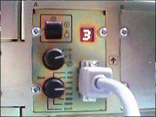
Picture 3: The CPU Patch Panel, sometimes called the
"bulkhead"
The two-position switch is for halt enable/disable ("dot in circle"
is enabled).
The LED display is for displaying the power-up test countdown
The three-position rotary switch is for selecting power-up modes ("arrow":
normal operation", "face": language inquery mode, "T in circle": test loop
mode)
The eight-position rotary switch is for selecting the baud rate for
the console terminal (from 300 baud to 38400)
The male DB9 connector is for the console. It's not a 9-pin PC serial port! You must have a Digital BCC08 cable, or build one. The pinout is:
DB9 (VAX) DB25 (PC)
1  ----------->  1
2  ----------->  3
3  ----------->  2
4  ----------->  5
5  ----------->  6
6  ----------->  20
7  ----------->  7
8  --\
9  --/
This is in general a null modem cable (pins 2-3, 3-2, 7-7, with the 8th and 9th pin on the VAX-side shorted; speaking from experience, you don't need all the pins that are connected in the BCC08 cable).
The KA630 has two operating states. One is normal operation (programmed I/O), the other is console I/O. Console I/O is entered when the "Halt enable/disable" switch on the CPU Patch Panel is in the enable position and a/ the "Halt" button on the system control panel is pressed b/ upon power-up. You are also dropped into console mode, when something fatal occurs to the operating system. You can identify the console state from the "chevron" prompt:
>>>You can enter bootstrap/diagnostic commands form this prompt (e.g. you can play around with memory locations, registers, etc).
BOOT </qualifier> [DEVICE]
Boots the specified device (DUxy for disks where x
is the controller number, y is the disk on that controller, MUxy
for TMSCP tapes (in the same manner) XQA0 or XQB0 for Ethernet).
If no device is pecified, the system goes through the sequence discussed
at power-up tests. Qualifier: /R5:<value>
- the <value> gets passed to VMB (primary boot loader).
CONTINUE
The CPU starts instruction execution from the address in the PC (Program
Counter). No initialization is performed.
DEPOSIT [qualifier] <address> <data>
Deposits <data> into the address specified. Special address specifications
include PSL (Processor Status Longword), PC, SP (Stack
Pointer), Rx for register #x, + for the next location
(counted in the unit given with the qualifier), - the previous location,
* the last referenced location. Qualifiers: /b data size
is byte, /w data size us word, /l data size is longword,
/v address is in the virtual address space, /p physical memory,
/i internal processor register, /g general register, /u
access to console program memory locations, /N:<count> range
of the operation.
EXAMINE [qualifier] <address>
Examines the data at the given address. The qualifiers are the same
as with DEPOSIT.
INITIALIZE
Processor initialization.
HALT
No effect, as the processor is in the halt state when in console I/O
mode.
REPEAT <command>
Repeats <command> until CTRL+C is pressed.
START <address>
Starts instruction execution at <address>
TEST [test number]
The test denited by [test number] is invoked (from 3-7 and B). If no
number is specified, no test is performed.
UNJAM
I/O bus reset.
The commands can be abbreviated (e.g. it's enough to type I for INITIALIZE, etc). Later/other MicroVAX CPUs had more complex console commands.
Whenever an error occures, the KA630 dumps a small error message on the console, which consist of a two-digit hexadecimal number, a small, abbriviated message, and the content of the PC.
+-----------------------------------------------------------------------------+
|HEX VALUE|   MESSAGE   |         EXPLANATION                                 |
+-----------------------------------------------------------------------------+
  02        EXT HLT         Break was typed on the console, QBINIT or QHALT
                            was asserted.
  04        ISP ERR         In attempting to push state onto the interrupt
                            stack during an interrupt or exception, the
                            processor discovered that the interrupt stack was
                            mapped NO ACCESS or NOT VALID.
  05        DBL ERR         The processor attempted to report a machine check
                            to the operating system, and a second machine check
                            occurred.
  06        HLT INST        The processor executed a HALT instruction in kernel
                            mode.
07 SCB ERR3 The vector had bits <1:0> equal to 3.
08 SCB ERR2 The vector had bits <1:0> equal to 2.
  0A        CHM FR ISTK     A change mode instruction was executed when
                            PSL<IS> was set.
  0B        CHM TO ISTK     The exception vector for a change mode had
                            bit <0> set.
  0C        SCB RD ERR      A hard memory error occurred while the processor was
                            trying to read an exception or interrupt vector.
10 MCHK AV An access violation or an invalid translation
  11        KSP AV          An access violation or an invalid translation
                            occurred during processing of an invalid kernel
                            stack pointer exception.
  15        CORRPTN         The console database was corrupted. The console
                            program simulates a power-up sequence and
                            rebuilds its database.
  16        ILL REF         The requested reference would violate virtual
                            memory protection, the address is not mapped,
                            the reference is invalid in the specified
                            address space, or the value is invalid in the
                            specified destination.
17 ILL CMD The command string cannot be parsed.
18 INV DGT A number has an invalid digit.
  19        LTL             The command was to large for the console to
                            buffer. The message is issued only after receipt
                            of the terminating carriage return.
  1A        ILL ADR         The address specified falls outside the limits
                            of the address space.
  1B        VAL TOO LRG     The value specified does not fit in the
                            destination.
  1C        SW CONF         For example, two different data sizes are
                            specified with an EXAMINE command.
1D UNK SW The switch is unrecognized.
  1E        UNK SYM         The symbolic address in an EXAMINE or DEPOSIT
                            is unrecognized.
  1F        CHKSM           The command or data checksum of an X command
                            is incorrect. If the data checksum is
                            incorrect, this message is issued and is not
                            abbreviated to "Illegal Command".
                            occurred during machine check exception
                            processing.
20 HLTED The operator entered a HALT command.
  21        FND ERR         A FIND command failed either to find the RPB or
                            64 kb of good memory.
  22        TMOUT           During an X command, data failed to arrive in
                            the time expected.
23 MEM ERR Parity error detected.
24 UNXINT An unexpected interrupt or exception occurred.
40 NOSUCHDEV No bootable devices found.
41 DEVASSIGN Device is not present.
42 NOSUCHFILE Program image not found.
43 FILESTRUCT Invalid boot device file structure.
44 BADCHKSUM Bad checksum on header file.
45 BADFILEHDR Bad file header.
46 BADIRECTORY Bad directory file.
47 FILNOTCNTG Invalid program image file.
48 ENDOFFILE Premature end of file encountered.
49 BADFILENAME Bad file name given.
4A BUFFEROVF Program image does not fit in available memory.
4B CTRLERR Boot device I/O error.
4C DEVINACT Failed to initialize boot device.
4D DEVOFFLINE Device is offline.
4E MEMERR Memory initialization error.
4F SCBINT Unexpected SCB exception or machine check.
  50        SCBZNDINT       Unexpected exception after starting program
                            image.
51 NOROM No valid ROM image found.
52 NOSUCHNODE No response from load server.
53 INSFMAPREG Invalid memory configuration.
54 RETRY No devices bootable, retrying.
Back to the top
Back to "Qbus modules"
Full Table of Contents
Back to the main page
| Created by: Ákos Varga | Last modified: |